Written by: Ian Jonas Yam

Sunday, December 1, 2013

Standard Terminal Markings of DC (Direct Current) Motors

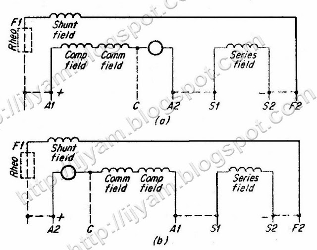
Standard terminal markings, as developed by NEMA, are given for series, shunt and compound motors in figure 1, figure 2 and figure 3 respectively. These figures all show compensating-field as well as commutating-field windings since they are intended to cover both fractional horsepower and integral horsepower motors. Fractional horsepower motors do not generally use compensating windings and they may not use commutating-field (interpole) windings.

The markings are combinations of letters and arabic numerals, generally, these are as follows:

- Armature - A1, A2
- Control signal lead - C
- Series field - S1, S2
- Shunt field - F1, F2
NEMA Standard terminal markings and connections for DC series motors.
Figure 1: NEMA Standard terminal markings and connections for DC series motors.

NEMA Standard terminal markings and connections for DC shunt motors.
Figure 2: NEMA Standard terminal markings and connections for DC shunt motors.

NEMA Standard terminal markings and connections for the compound, or stabilized shunt motors. (a) counter-clockwise rotation; (b) clockwise rotation
Figure 3: NEMA Standard terminal markings and connections for the compound, or stabilized shunt motors. (a) counter-clockwise rotation; (b) clockwise rotation


Related post:


Did you enjoy reading this post, then consider subscribing by Email to Technovation - Technological Innovation and Advanced Industrial Control Technologies

No comments :

Post a Comment

Leave a comment!
Add your comment below:

Related Posts Plugin for WordPress, Blogger...

ShareThis